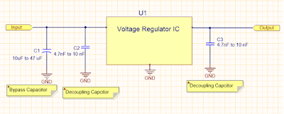
Bypass Capacitors
The main function of the bypass capacitor is to create an AC shunt to remove undesirable energy from entering susceptible areas. The bypass capacitor is acting as a high frequency bypass source to reduce the transient circuit demand on the power supply unit. Usually, aluminium or tantalum capacitor is a good choice for bypass capacitors, its value depends on the transient current demand on the PCB, but it is usually in the range of 10 to 47 uF. Larger values are required on the PCB with a large number of integrated circuits, fast switching circuits, and PSUs and having long leads to PCB.
Decoupling Capacitors
During active device switching, the high frequency switching noise created is distributed along the power supply lines. The main function of the decoupling is to provide localised source of DC power for the active devices, thus reducing switching noise propagating across the board and decoupling the noise to ground.
Ideally, the bypass and decoupling should be placed as close as possible to the power supply inlet to help filter high frequency noises. The value of decouupling capacitor is approximately 1/100 or 1/1000 of the bypass capacitor. For better EMC performance, decoupling capacitors should be placed as close as possible to each IC, because trace impedance will reduce the effectiveness of decoupling function.
Creamic capacitors are usually selected for decoupling; choosing the value depends on the rise and fall times of the fastest signal. For example, with a 33 MHz clock frequency, use 4.7nF to 100nF, with a 100 MHz clock frequency use 10nF.
Apart from the capacitance value when choosing the decoupling capacitor, the low ESR of the capacitor also affects its decoupling capabilities. For decoupling, it is preferable to choose capacitors with a ESR value less than 1 ohm.

No comments:
Post a Comment